

See when horizontal benders, ironworkers, and plate rolls can reduce press brake bottlenecks and improve shop flow
Bending remains a common bottleneck for fabricators, and it’s easy to see why. Parts are cut in short order. Then they hit the press brake department, and that rapid part flow stalls.
Offline programming with bend simulation can help here, along with the right tooling investment, especially when running them for the first time. Such capabilities help streamline complex orders significantly, but they don’t solve every constraint in bending, especially in high-product-mix environments. Sometimes, buying another press brake might not be the best approach.
To uncover alternatives, The Fabricator spoke with Matt Weeks, director of sales, and Ben Flamholz, vice president, at Trilogy Machinery, Belcamp, Md. They broke down alternative forming technologies into three categories: one to handle small, usually simple workpieces; another to handle certain prototyping and one-off jobs; and a third to handle certain large-radius geometries.
The overall strategy is simple: When you use the best forming technology for the job as often as possible, you can minimize or even eliminate the forming constraint.
Streamline Small-Workpiece Bending
Imagine you have a forming department with new press brakes, a CNC folder with a bidirectional folding beam, and a CNC panel bender. You recently sold your old press brakes, mainly because they were past their useful life. Old controllers made operating them difficult, and significant ram upset caused their beds to bow. Repairing that “old iron” just didn’t make economic sense.
The strategy works, at least at first. The new press brakes with multiaxis backgauges and modern tooling bend the most complex jobs quickly and easily. But then you notice something: New press brakes with touchscreen controls and umpteen-axis backgauges are now being tied up with work that just needs a simple 90-degree bend.
As Flamholz explained, this scenario could benefit from a lesser-known press brake alternative: the horizontal bending machine. Picture a press brake tool and die, but on its side. The operator calls up a program, inserts the punch and die, places the blank against a gauge (similar to a backgauge finger, just positioned to the side of the bend area), then initiates the bend cycle.
These machines accept a variety of press brake tool and die sets, including certain European- and American-style segmented tools that can be adapted for horizontal bending. Tangs on the punches and dies seat into the machine’s toolholders just as they would on a press brake. They also have wheel tools and other special tooling for making large-radius bends and specialty parts.
The hydraulic cylinder pushes the tool directly, with the largest machines able to apply more than 80 tons of force. Because bend lengths are short and force is applied from the center, “you don’t need to deal with deflection or compensation through crowning, as you do with a typical press brake,” Flamholz said.
The machine operates with just one toolset at a time. This limitation, Flamholz said, really defines the machine’s purpose: to remove certain work from the regular forming workflow. Its controller can save multiple programs and setups. And the backgauge is programmable, too, so it can handle parts with several bends.
The machine frees a large-bed press brake to handle large parts and a small electric CNC press brake to form small, very complex parts (say, with small internal flanges as well as positive and negative bends). Meanwhile, the horizontal bender handles simpler jobs with bend lengths less than 12 in.
The machine does not offer the flexibility of a CNC press brake, of course. Offline bend simulation isn’t possible. And you can’t use the horizontal bender to stage-bend with multiple common-shut-height toolsets.
Even so, Flamholz clarified that the horizontal bender is still a CNC machine with precision positioning. A fabricator might spend time programming a complex part to take advantage of the horizontal bender’s strengths, including the ability to lift a formed piece vertically out of the tooling. With just one punch and die set, there’s no danger of work becoming “trapped” at the end of a bend sequence.
Flamholz described some horizontal bending applications in which workpieces were formed into round, square, or rectangular shapes that close behind the punch tool. Such forms wouldn’t be possible on a brake, of course, with the ram or body of the punch colliding with the part. “With the horizontal bender, the operator just lifts the part off the machine.”
Forming for Prototyping
Say you have one-off jobs, those for prototypes or one-time projects. You break into production work to form the part, then resume production, sometimes multiple times a shift. Forming accuracy requirements vary widely. The new machines can handle them easily, but the interruptions do break the flow of production, sometimes significantly.
As operations scale, they sometimes separate low-quantity work into its own quick-response cells—say, with a small-bed cutting machine next to a small forming machine and other equipment. Still, demand might not be consistent. Moreover, if you have a forming department bottleneck, managers might “steal” some forming capacity at the quick-response cell—especially if there’s a precision press brake just sitting there, waiting to be used.
Moreover, the cell’s sheer variety of work might slow things down. The cell might cut, bend, and insert hardware for low-quantity rush orders for established customers. Programs have already been established. Orders flow through different machines in the cell within minutes.
At the same time, however, the cell also processes prototyping work. Drawings might not be complete and procedures aren’t quite established. Such work requires skilled people who can fine-tune setups and experiment. The best way to fabricate the part just hasn’t been established yet.
As Flamholz explained, another forming alternative could help here: an ironworker with a press brake attachment. Imagine the ironworker in a separate area of the shop, one dedicated to prototypes for customers as well as internal work: parts to build assembly fixtures, internal signage, and other miscellaneous items. It could also handle those simple jobs for customers that don’t require all the capabilities of a CNC press brake.
“These press brake attachments have various tooling options,” Flamholz said, “including a four-way lower die that works for gauge material. And depending on the size of the machine, the brake attachment [can have a bed] that’s anywhere from 20 to 28 in. wide, where you can form 3/16-in. material and thinner.” He added that some attachments designed to handle thicker material come in shorter lengths, between 10 and 12 in. “The tonnage is spread over a much smaller area” compared to a typical press brake.
The ironworker brake attachment has its limitations, of course, one being the available stroke, which maxes out at 4 in. (this isn’t a machine for deep box bending), as well as a limit on bend length. Force is applied in the center of the bed. This means the bend can be only so long before deflection on the far right and left side of the bed becomes an issue.
Also, the attachment isn’t programmable. Instead, the operator sets the ram’s depth of penetration. To position the bend, he can use a manually set backgauge, rely on scribe lines (usually made on a separate machine), or use a “homemade” gauge.
As with any technology, how the brake ironworker attachment is used depends on the market a fabricator serves. But as Flamholz explained, in most cases, the ironworker brake attachment often works best in the prototyping or miscellaneous fabrication cell, where experienced, hands-on craftspeople fabricate one-off creations.
“The ironworker is a multifunction machine with a small footprint. You can move from shearing to punching to bending,” Flamholz said, adding that such systems can be valuable additions for the right kind of work.
The Large-Radius Bend
Bending large radii also can cause some forming roadblocks. For large radii near the edge, bump bending (otherwise known as incremental or step bending) on the brake can work well, especially if the machine has a mutiaxis backgauge that gives the operator a solid gauging point. Panel benders and folders can bump these incremental bends very efficiently.
That said, step bending also leaves a noticeable mark for each bend line. Some might set a finer pitch (space between steps), but this alone doesn’t eliminate the marks. Also, when radius bends move away from the plate edge (picture a radius bend in the middle of two long flat sections), finding a consistent gauge point for every bump can become challenging.
A toolset involving a large die opening and a round punch can work, especially if each bend involves a single hit. But if the radius requires the tooling to make several hits, the job starts to become challenging and repeatability might be an issue.
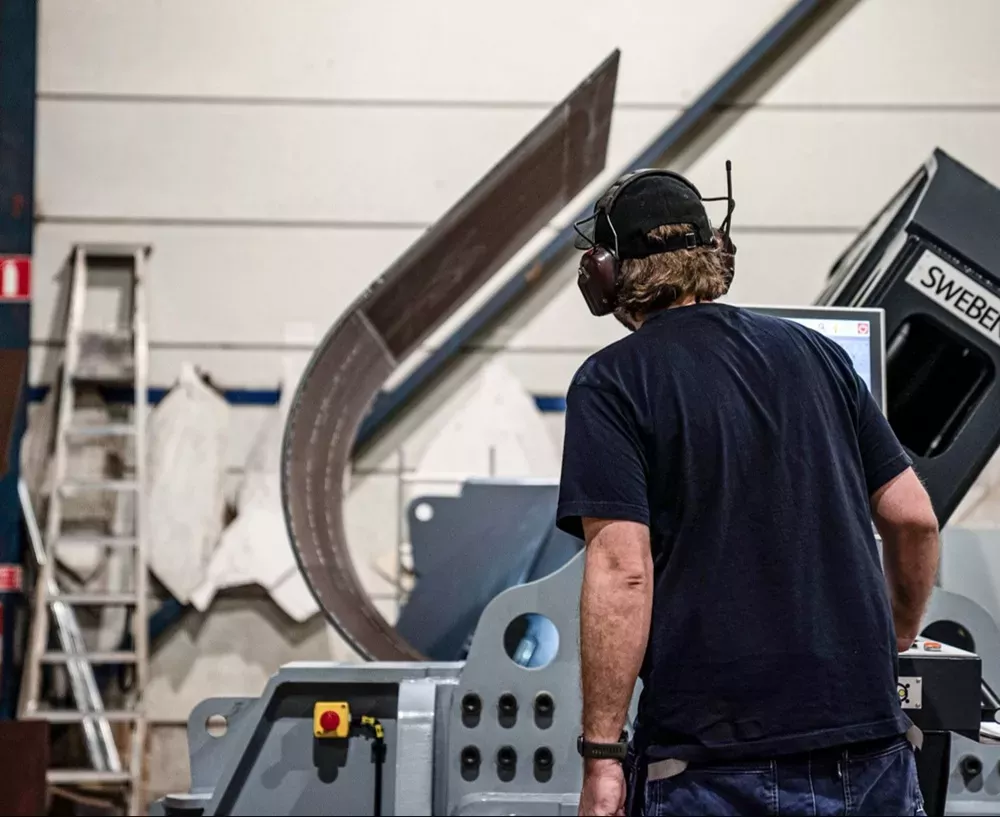
For these and other specialty jobs, Weeks described a technology many don’t think about, especially for noncylindrical shapes: the plate roll. The rolling process largely eliminates those bend lines. With the right setup and machine technology, the process often never lets go of the workpiece. The rolls grasp the work, then move as programmed to create the radius forms.
This can include multiradius forms, like those found in excavator buckets. As Weeks explained, bumping on a press brake can get quite involved, requiring the operator to determine the optimal pitch and degrees of bend for each step when transitioning from one radius to another. On a plate roll, especially one with a programmable CNC, forming multiradius parts often isn’t quite as arduous.
“With a CNC plate roll, you have interpolation, where the side bend rolls move [on a specified path, toward and away from the top roll] as they’re rotating. This allows you to control that radius transition.”
Double-pinch four-roll CNC machines are able to prebend both ends of a plate (to minimize unbent flat sections) before commencing the rolling cycle. “The issue with initial-pinch three-roll machines is that you need to physically take the sheet out, rotate it, and run the other edge through to get that second prebend,” Weeks said.
Of course, noncylindrical shapes with long flat sections likely won’t need prebending, so the three-roll’s prebending limitation might be a nonissue. That said, if a shop is looking to transfer a part that used to be bumped on a brake, a CNC plate roll offers the ability to program and track the material position throughout the forming process.
“There’s an encoder that tracks the rotation of the rolls, which are driving the plate through the machine,” Weeks said, “so the machine always knows where the plate is located. This gives you the ability to stop and start a bend precisely where you need it to.”
Weeks described an application where a CNC four-roll system was used to create a large-radius bend, after which the piece was transferred to a press brake to form a return flange. In this case, bumping took a lot of finesse at the press brake, and the CNC rolling process had the added benefit of no bump lines on the part’s outside radius.
Rolls can also tilt to form cones or other irregular shapes. The process still involves some trial and error, since the material on one side needs to slide forward during the forming cycle. Careful material handling could be involved as well. Still, the operation is likely to be much easier than it would be on a high-tonnage press brake, where you’d have a more-art-than-science process involving overhead cranes (to hold the work), operator finesse, and a significant amount of patience.
The plate roll does have its limitations. First, it needs somewhere to grasp the material, so it always leaves unbent flat sections near the plate edges. To minimize the unbent flat sections, the operator prebends the plate edges—usually on the plate roll itself, but sometimes on the press brake, especially when the radius needs to go nearly all the way to the plate edge. Press brakes and plate rolls complement each other well here.
But again, if you’re using a plate roll to form a noncylindrical object, where the bends are far away from the plate edge anyway, then the unbent flat section isn’t an issue. What can be an issue, however, is the range of sheets and plates the rolls can handle.
Press brakes can form anything as long as the job’s forming tonnage falls below the tonnage limit of the machine and tooling. Plate rolls, on the other hand, are engineered to roll only a specific thickness range of material. Material yield strength also comes into play. Accounting for all this involves some level of crowning—with the roll diameters slightly larger in the middle than on the ends—to compensate for deflection.
Another limitation is the range of radii a roll can form, especially on smaller-radius jobs. No matter how much forming power a plate roll has, it can’t make a bend that’s smaller than the diameter of the top roll.
And for machines rated for thick material, those top rolls can be only so small. Machines rated for thinner gauges can have small top-roll diameters that can form tighter-radius workpieces. But if you’ve got a radius bend in thick material, you need to ensure specific bend radii are possible.
Alternatives exist, including machines with backup rolls that mitigate deflection, allowing smaller-diameter rolls to form thicker materials. Of course, this comes with trade-offs. For instance, top backup rolls need to be moved out of the way to form complete cylinders.
Rolls also can be machined with grooves and other pockets to handle previous bends made on a press brake. Whether this makes economic sense depends on the volumes involved. But as Weeks described, such tooling modifications are available—and they show just how complementary a press brake and plate roll can be.
Bend direction is another limitation. “When you use a plate roll, you’re almost always using it to bend a radius in one direction,” Weeks said. “It’s possible to take the sheet out and flip it, but you have limitations there. In most cases, if you have positive and negative bends, it’s easier to form it on a press brake.”
Weeks added one more point: Whether you’re bumping or rolling, you still need to account for material thickness and hardness variation. “When you bump on a press brake, you’re bending against three points of contact,” he said: the punch tip and the two die shoulders. “When you roll, you’re still elongating the material, which is why you’re still subject to material variation.”
Certain challenging applications, like abrasion-resistant steel plate, might benefit from one technology or the other, depending on the radius being formed. “But overall, the mechanics behind forming doesn’t change,” Weeks said.
Manage the Flow
Which technology to use depends on the mix of work a shop processes. But as sources explained, the idea is to observe those bending bottlenecks: complicated bump bending and the simple, sometimes high-quantity work that steals capacity from high-end press brakes capable of doing so much more.
The bottom line: Match the right forming technology with the right kind of work. With that, bending constraints can be mitigated, and work through the forming department starts to flow.